Virtual Switches
Added in version 9.1.
Important
Virtual Switches are supported on HVM layout 2.0 with HVM OS 26.04. Legacy and layout 1.3 clusters use OVS networking; see HVM Networks.
Virtual Switch Overview
A Virtual Switch is a cluster-level networking abstraction that simplifies host network configuration across layout 2.0 HVM compute nodes. Rather than manually configuring bridges, bonds, and VLANs on each host via CLI, Virtual Switches allow administrators to define network intent once and have it applied consistently across the entire cluster.
Virtual Switches manage:
Uplink selection — Which physical NICs carry traffic
Bond creation — Aggregating multiple NICs for redundancy or throughput
Traffic separation — Isolating VM, storage, migration, and SDN traffic
VLAN handling — Tagging traffic for network segmentation
IP addressing — Assigning host-level IPs for storage and migration networks
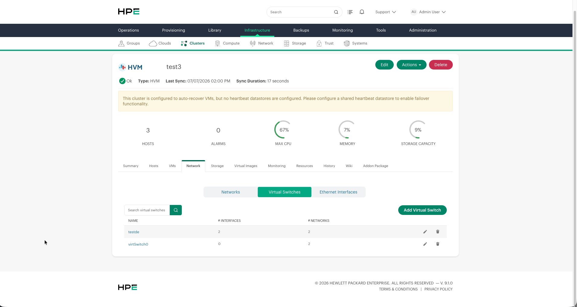
Each layout 2.0 HVM cluster supports up to 8 Virtual Switches. A default Virtual Switch named vs0 is created automatically during cluster provisioning and handles VM network traffic.
Default Virtual Switch Behavior (vs0 — General)
When a cluster is provisioned, a default Virtual Switch called vs0 (type: General) is created on the management interface. Understanding its default behavior is critical before adding additional segments:
Default traffic on the management interface:
Live Migration traffic flows over the management interface by default, even if no explicit Live Migration segment has been created. A dedicated Live Migration segment is only required when you want to isolate migration traffic onto a separate VLAN or subnet.
Data storage traffic (NFS and iSCSI) can also flow over the management interface through
vs0by default. Creating dedicated Data segments is recommended for performance and isolation in production environments.
Adding segments to vs0:
When you edit vs0 to add Data (General) and/or Live Migration segments on the same Virtual Switch as the management interface, VLAN tagging is required:
Adding Data (General) requires a VLAN tag and a dedicated IP subnet for storage traffic.
Adding Live Migration requires a VLAN tag and a dedicated IP subnet for migration traffic.
If both are added to the same Virtual Switch, each must have its own VLAN and subnet.
Splitting Data and Live Migration onto different networks:
When both Data (General) and Live Migration are selected on the same Virtual Switch, a checkbox appears: “Data (General) and Live Migration are on different networks”. When enabled:
Two separate VLAN tags are required (one for Data, one for Live Migration)
Two separate IP subnets must be configured
This provides full isolation between storage and migration traffic while sharing the same physical uplinks
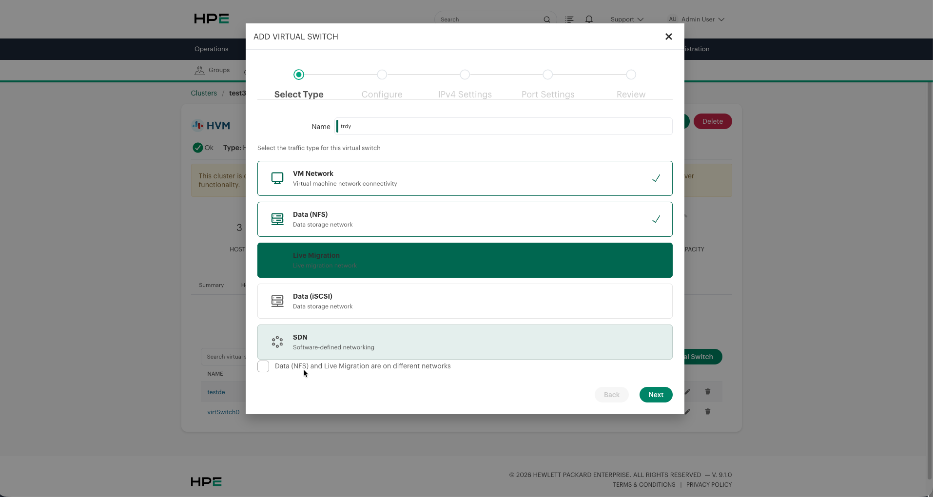
Key constraint: Only one Live Migration interface is supported per cluster. If you configure Live Migration on a Virtual Switch, no other Virtual Switch in the same cluster can carry Live Migration traffic.
Navigating to Virtual Switches
To access Virtual Switches:
Navigate to and select your HVM cluster
Click the Network tab
Select the Virtual Switches sub-tab
The list view displays all Virtual Switches with their name, number of interfaces, and number of associated networks. From here you can add, edit, or delete Virtual Switches.
Traffic Types
Each Virtual Switch carries one or more traffic types that define what kind of network communication flows through it. When creating a Virtual Switch, you select which traffic types it will handle.
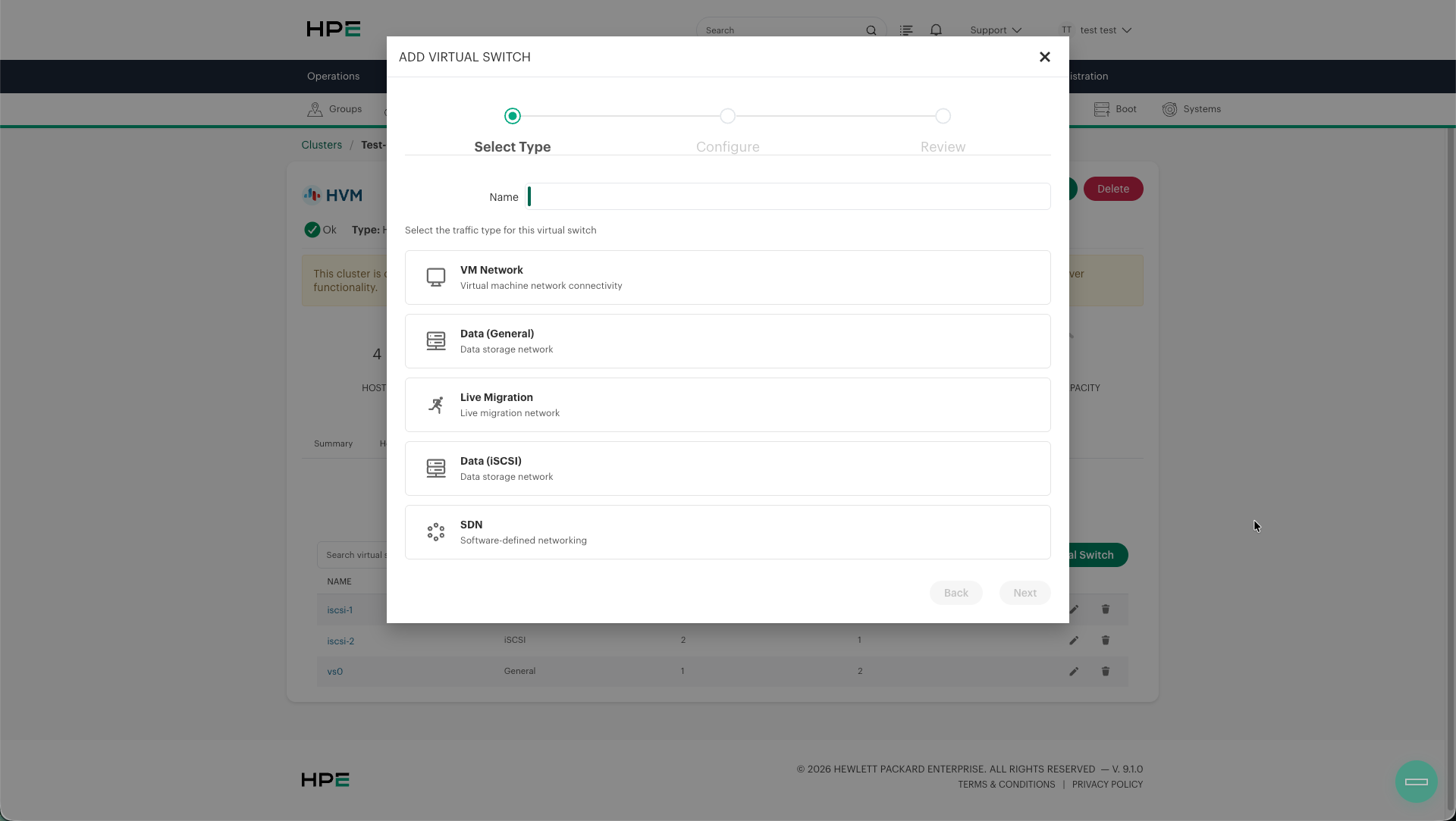
The available traffic types are:
Traffic Type |
Description |
Use Case |
|---|---|---|
VM Network |
Virtual machine network connectivity. Uses a VLAN-aware Linux bridge for VM-to-network communication. |
Required for VMs to communicate with external networks |
Data (General) |
NFS storage network for shared datastores. Supports bonding for redundancy and throughput. |
Connecting hosts to NFS-based shared storage |
Live Migration |
Dedicated network for live migrating VMs between hosts with minimal downtime. |
Enabling live VM migration across cluster hosts |
Data (iSCSI) |
iSCSI storage network. Uses a single interface (no bonding) to support multipath I/O. |
Connecting hosts to iSCSI SAN storage |
SDN |
Software-defined networking. Dedicated pathway for SDN control and data plane traffic. |
Environments using SDN controllers (e.g., CN2) |
Traffic Type Combination Rules
Multiple traffic types can be combined on a single Virtual Switch, subject to the following rules:
Traffic Type |
Bonding |
Single NIC |
Can Share With |
Notes |
|---|---|---|---|---|
VM Network |
Yes |
Yes |
Live Migration, Data (General) |
Default Virtual Switch type |
Data (General) |
Yes |
Yes |
VM Network, Live Migration |
Supports bonds for throughput |
Live Migration |
Yes |
Yes |
VM Network, Data (General) |
Cannot share with iSCSI |
Data (iSCSI) |
No |
Yes |
Cannot share with other data types |
Single NIC enforced for multipath |
SDN |
Yes |
Yes |
Cannot share with other types |
Requires dedicated Virtual Switch |
Important
iSCSI requires a dedicated Virtual Switch with a single NIC per host. Bonding is not supported because redundancy is provided by iSCSI multipath at the protocol level.
SDN requires its own dedicated Virtual Switch and cannot coexist with other traffic types.
Data (General) and Live Migration can optionally be split onto different networks (separate IP ranges) even when on the same Virtual Switch.
Combining Traffic Types
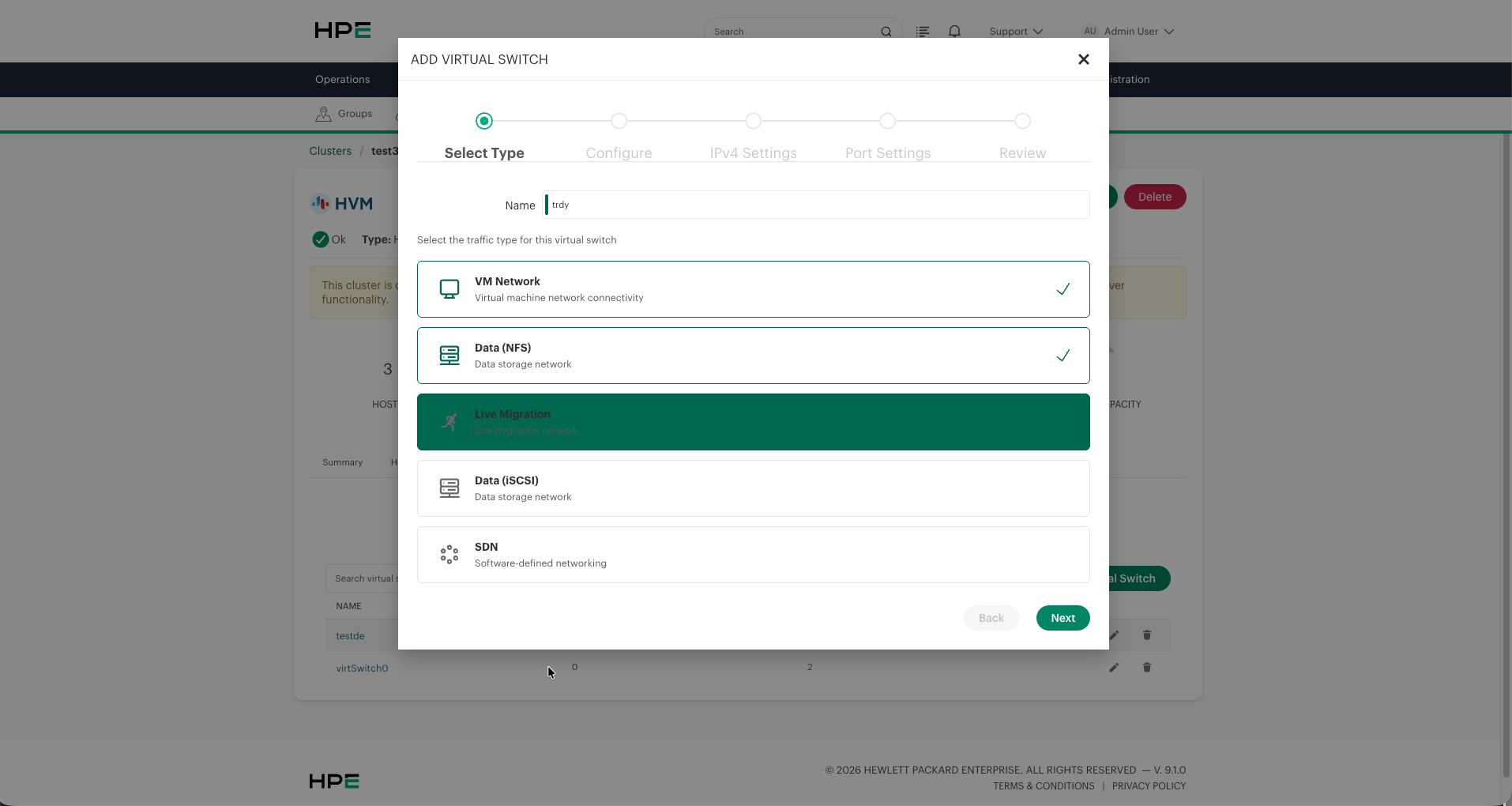
You can select multiple traffic types for a single Virtual Switch. When combining types, the wizard adapts:
Selecting VM Network + Data (General) + Live Migration enables a 5-step wizard (Select Type → Configure → IPv4 Settings → Port Settings → Review).
When both Data (General) and Live Migration are selected, a checkbox appears: “Data (General) and Live Migration are on different networks”. Enabling this allows you to assign separate IP ranges to each traffic type.
Virtual Switch Prerequisites
Before creating a Virtual Switch, ensure the following:
Physical NICs are cabled and up on each host that will participate in the Virtual Switch.
Upstream switch ports are configured for the desired mode (access/trunk, VLAN IDs, and LACP when using 802.3ad).
Consistent NIC naming across hosts if using uniform uplinks, or identify per-host NIC names in advance.
MTU support end-to-end — All devices in the network path (switches, routers, storage arrays) must support the configured MTU (especially 9000 for jumbo frames).
iSCSI multipath should be configured at the OS/protocol layer if using iSCSI storage.
If a newly installed physical NIC is not available for selection, first add and safely validate it in Netplan, use sudo hvmcli interfaces list --filter ethernet to confirm host discovery, and refresh the cluster in the UI. See Preparing HVM Hosts for the guarded procedure. Do not use a mutating hvmcli virtswitch command merely to make an OS interface appear in inventory.
Adding a Virtual Switch
Click Add Virtual Switch to launch the creation wizard. The wizard guides you through the following steps:
Step 1: Select Type
Enter a Name for the Virtual Switch (maximum 16 characters)
Select one or more traffic types for this Virtual Switch
Click Next
Note
The Virtual Switch name is limited to 16 characters as a storage constraint. The underlying Linux bridge, bond, and libvirt network interface names are assigned automatically from a cluster-scoped counter (for example hvmbr0, hvmup0, hvmnet0) and are independent of the Virtual Switch’s display name.
Tip
The default vs0 created during cluster provisioning can be renamed and edited, but it should not be deleted unless an alternative VM Network Virtual Switch is in place. At least one Virtual Switch with the VM Network traffic type must exist for VMs to have network connectivity.
Step 2: Configure
Configure the physical uplinks and bond mode for the Virtual Switch.
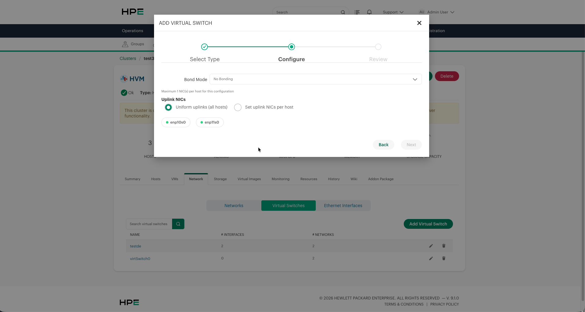
Bond Mode
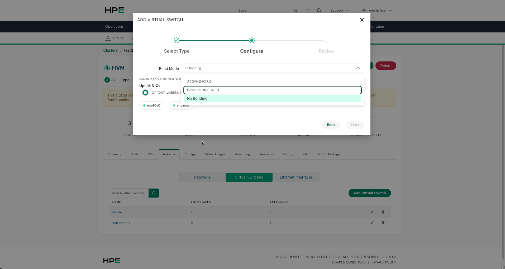
Select how multiple NICs are aggregated:
Bond Mode |
Description |
|---|---|
No Bonding |
Single NIC per host. No redundancy at the link level. Maximum 1 NIC per host. |
Active Backup |
One NIC active, one standby. Automatic failover if the active link fails. No switch-side configuration required. |
LACP (802.3ad) |
Both NICs participate in an 802.3ad bond. The connected upstream switch ports must belong to the same compatible LACP group. |
Warning
When using LACP (802.3ad), configure the upstream physical switch ports for the same LACP group before applying the Virtual Switch. Mismatched configurations can cause connectivity loss.
Important
Do not assume that an Active Backup bond receives universal MII polling, up-delay, or down-delay values automatically. These settings can vary by HVM release and networking backend, and automatic defaults are not guaranteed. Before carrying production traffic, inspect the effective bond configuration on each host and configure the required values explicitly through tooling supported by that HVM release. Use the product UI or hvmcli capabilities documented for the installed release; do not copy unverified values from another release or backend.
Uplink NICs
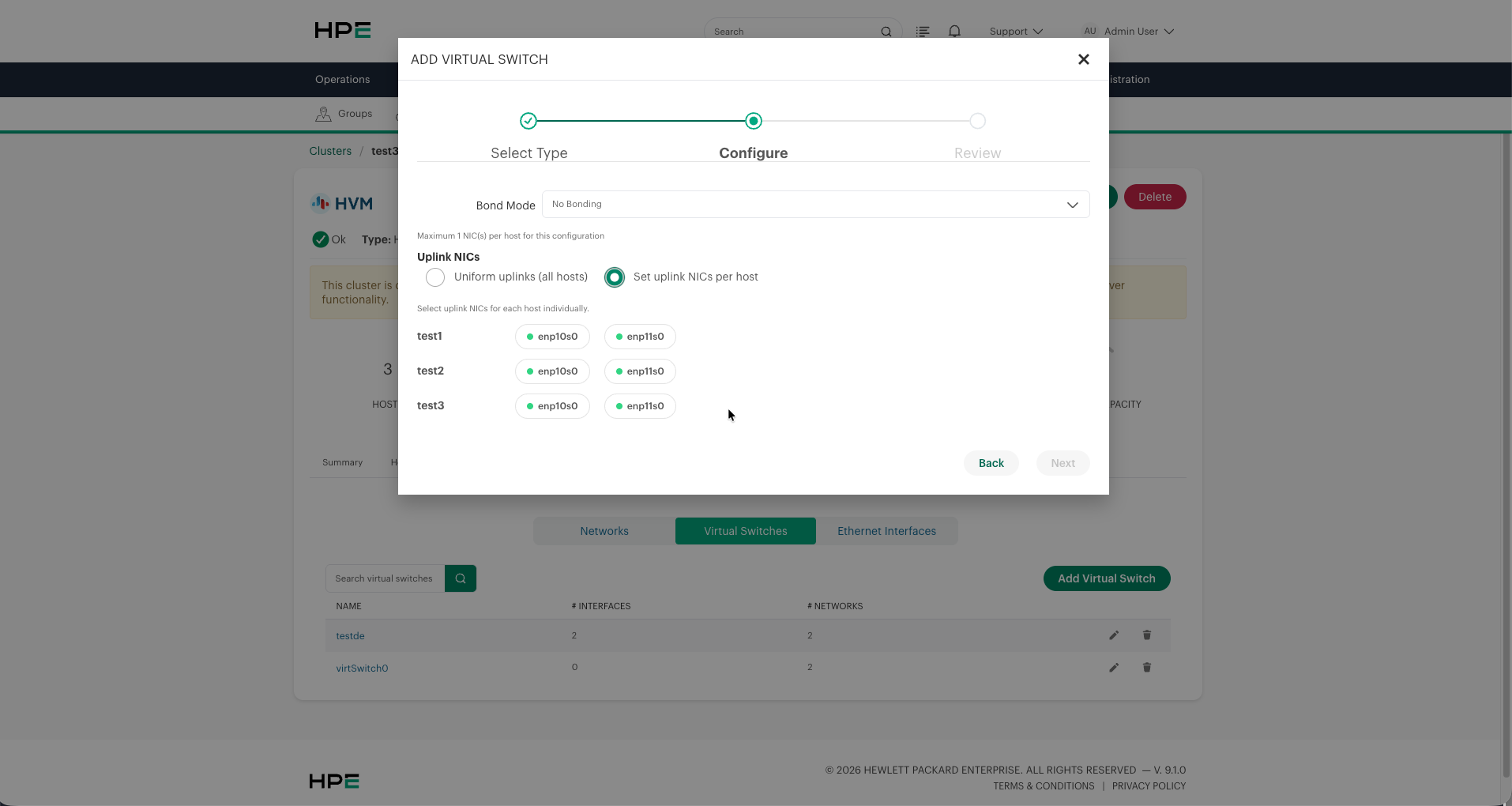
Choose how physical NICs are assigned to hosts:
Uniform uplinks (all hosts) — The same NIC(s) are used across all hosts. Select from the available interfaces shown as green-tagged buttons.
Set uplink NICs per host — Different NICs can be selected for each individual host. This is useful when hosts have heterogeneous NIC naming or hardware configurations.
Tip
Use Set uplink NICs per host when servers in the cluster have different NIC names (e.g., different hardware generations with different PCIe slot assignments).
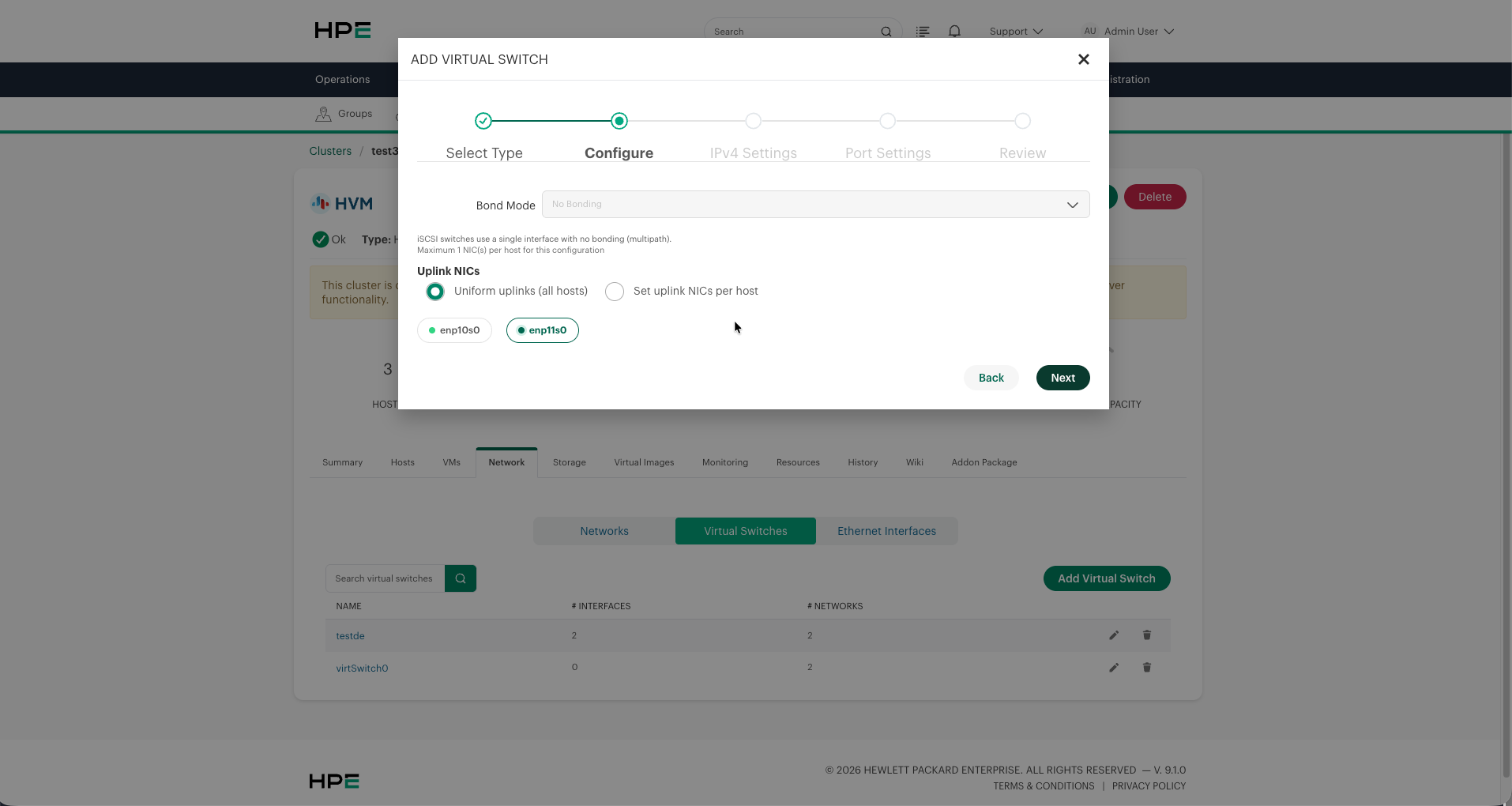
iSCSI Configuration
When Data (iSCSI) is the selected traffic type, the configure step enforces specific constraints:
Bond mode is locked to No Bonding
Maximum 1 NIC per host
This is because iSCSI relies on multipath I/O at the protocol layer for redundancy, not link-layer bonding.
Step 3: IPv4 Settings
Configure IP addressing for traffic types that require host-level IPs (Data and Live Migration networks). VM Network traffic does not require host IPs since VMs get their own addresses.
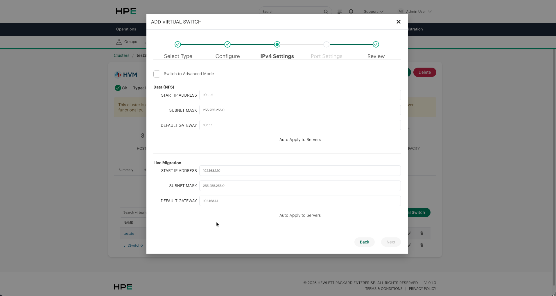
For each traffic type requiring IP configuration:
Start IP Address — The first IP in the range to assign to hosts. Each host in the cluster receives the next sequential IP.
Subnet Mask — Network subnet mask (e.g.,
255.255.255.0)Default Gateway — Gateway for this traffic network
Auto Apply to Servers — When enabled, the IP addresses are automatically distributed and applied to all current cluster hosts
Note
Gateways specified for Data (General), Live Migration, and iSCSI segments are stored as metadata only within the Virtual Switch configuration. They are not applied to the host routing table. Only the Management Gateway (configured during cluster provisioning) is actively used for routing. These gateway values are retained for documentation and future reference purposes.
When Data (General) and Live Migration are on different networks, separate IP configuration sections appear for each traffic type, allowing you to place them on different subnets.
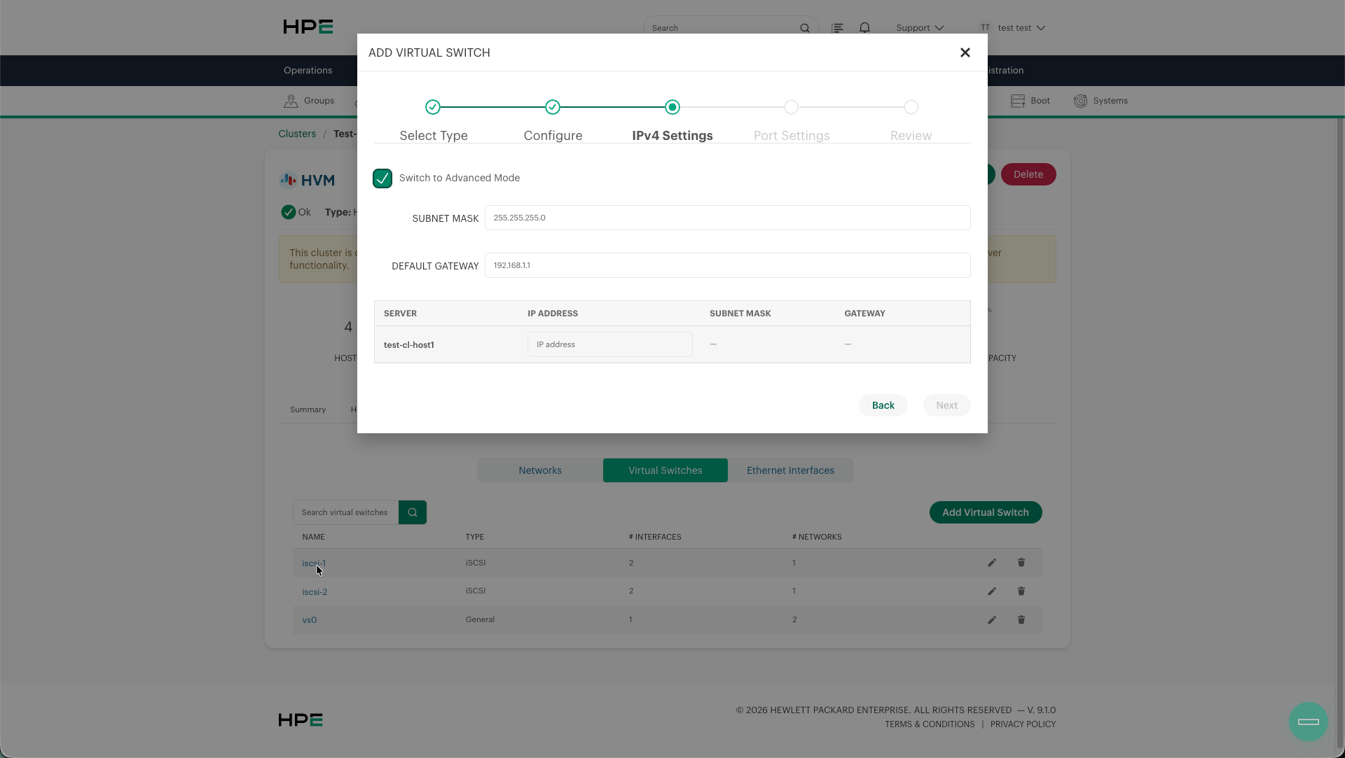
Switch to Advanced Mode — Enables per-host IP assignment for scenarios where automatic sequential allocation is not appropriate.
Step 4: Port Settings
Configure VLAN tagging and MTU settings.
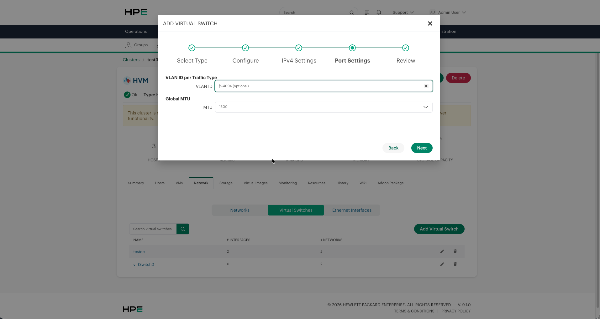
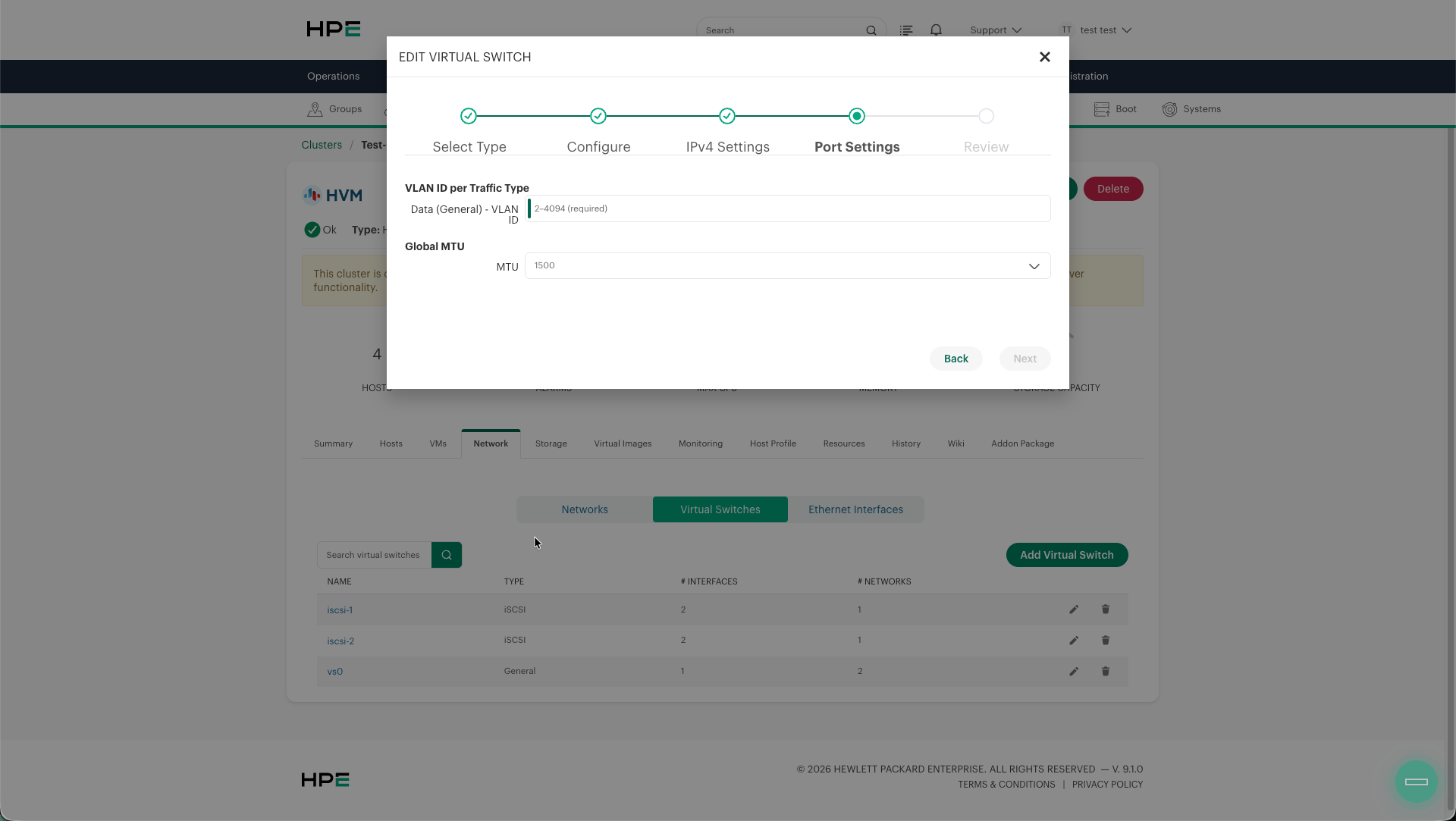
VLAN ID per Traffic Type — Optional VLAN tag (2–4094) applied to the traffic. When set, traffic is tagged with this VLAN ID on the physical uplink. Leave empty for untagged (native VLAN) traffic. VLAN 1 is reserved and cannot be specified.
Note
When a VLAN ID is configured, the upstream physical switch ports must be configured as trunk ports that allow the specified VLAN(s). Omitting the VLAN ID means the traffic is sent untagged on the native VLAN of the switch port.
Global MTU — Maximum Transmission Unit size for all interfaces in this Virtual Switch. Options:
1500 — Standard MTU (default)
9000 — Jumbo frames, when required by the network design
Important
Select MTU 9000 only when the complete path—including host interfaces, switches, routers, and storage endpoints—has been configured and validated for jumbo frames. Otherwise retain the default MTU 1500. The MTU is optional in the product configuration; 9000 is not a universal HVM requirement.
Step 5: Review
Review the complete Virtual Switch configuration before applying.
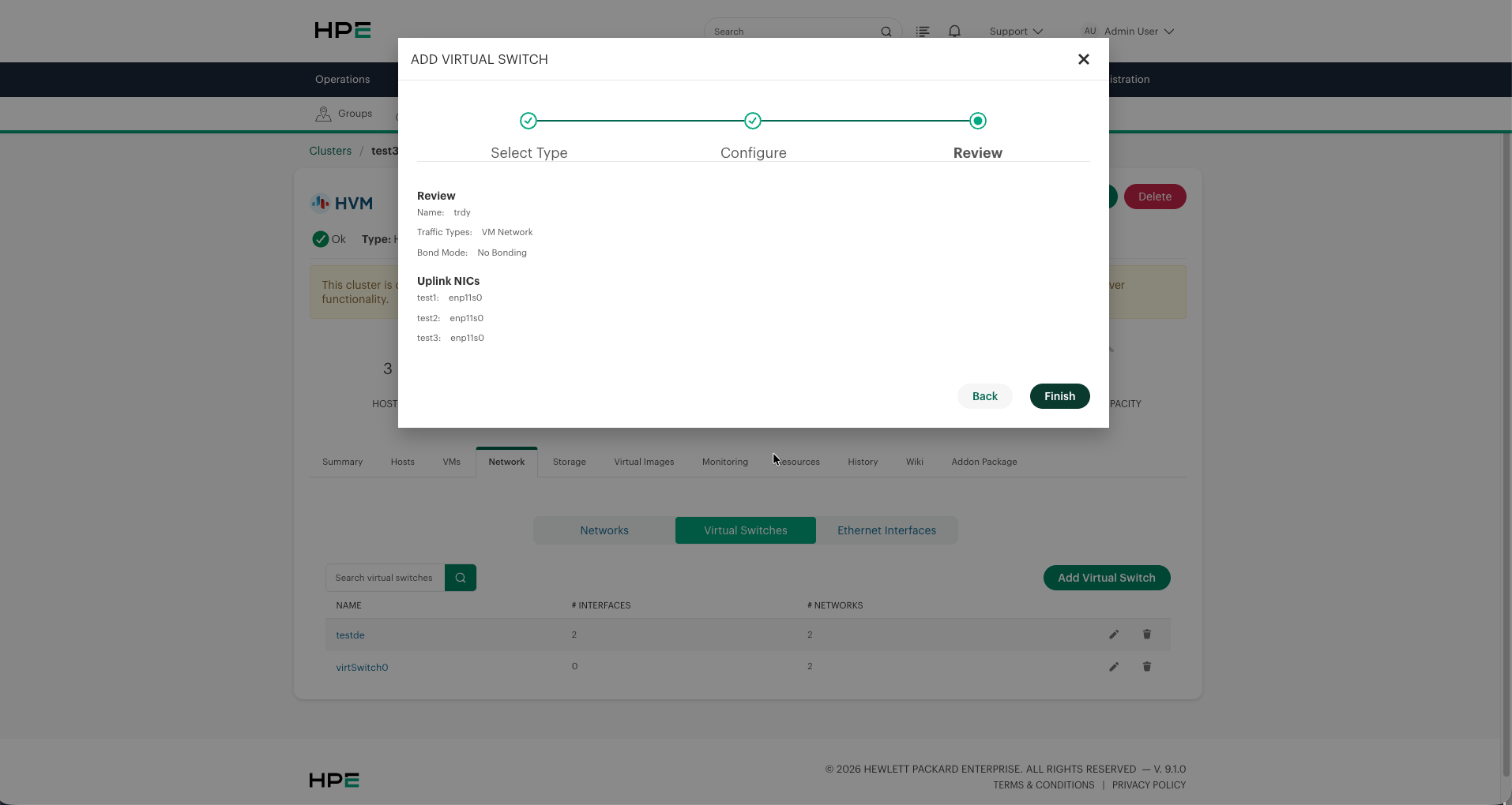
The review displays:
Name — Virtual Switch name
Traffic Types — Selected traffic types
Bond Mode — Bond configuration
Uplink NICs — Per-host NIC assignments
Click Finish to create the Virtual Switch. The configuration is applied to all hosts in the cluster.
Editing a Virtual Switch
Click the edit icon (pencil) next to a Virtual Switch to modify its configuration. You can change:
Uplink NICs (add/remove interfaces)
Bond mode
VLAN tags
MTU settings
IP addresses
Traffic types
Important
Editing a Virtual Switch that is actively carrying traffic may cause a brief network interruption as the new configuration is applied across hosts. Specifically, changing uplinks, bond mode, MTU, or VLAN settings will temporarily disrupt traffic on the affected networks. Plan these changes during a maintenance window for production environments.
Deleting a Virtual Switch
Click the delete icon (trash) next to a Virtual Switch to remove it. A confirmation dialog appears before the deletion proceeds.
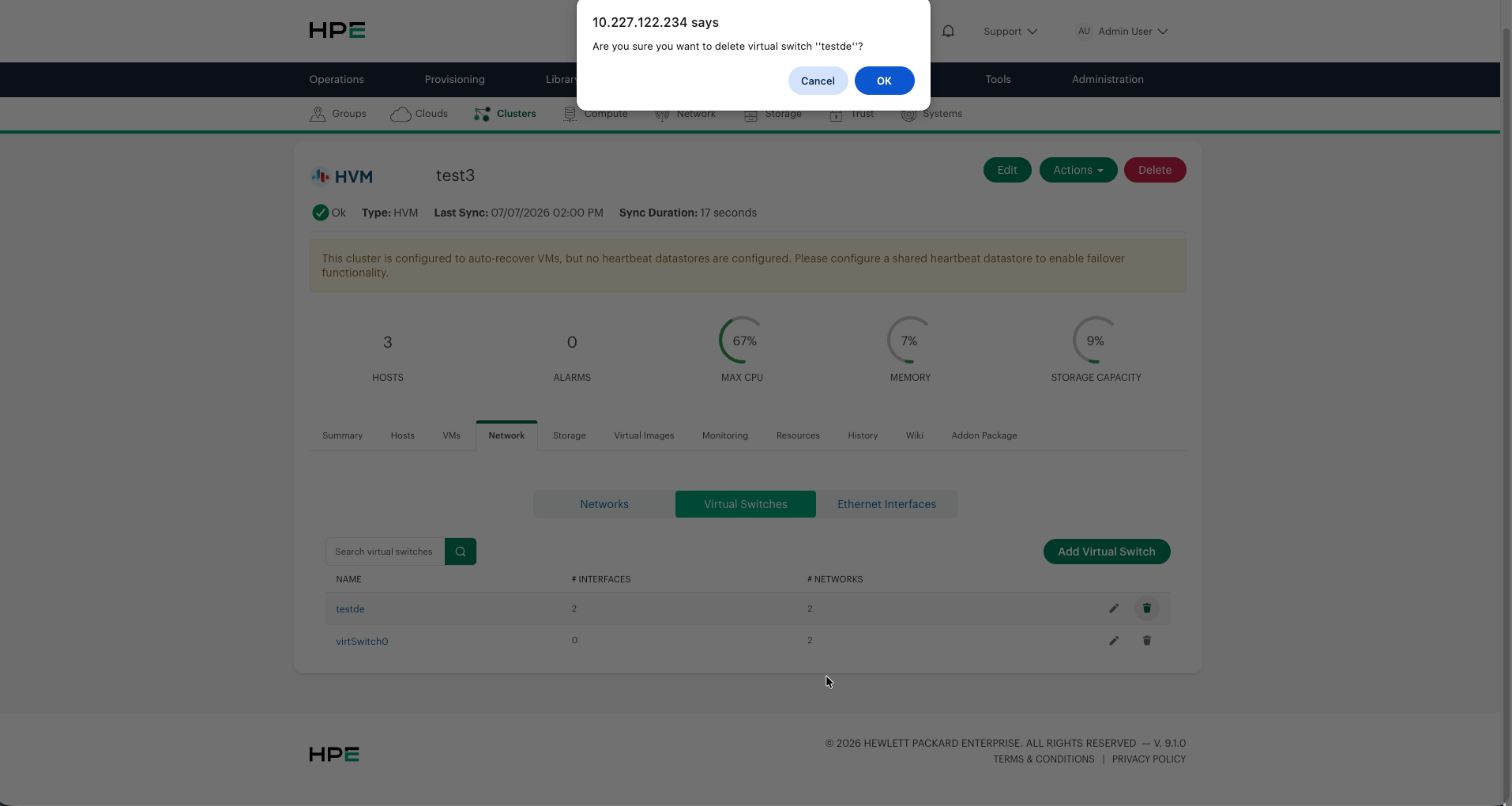
Warning
You cannot delete a Virtual Switch that has active VMs or networks attached to it.
Deleting a Virtual Switch removes all associated host networking configuration (bridges, bonds, VLANs) from every node in the cluster.
The default
vs0should not be deleted unless you have an alternative VM network configured.
Virtual Switch Best Practices
Network Design
Separate traffic types for production environments. Use dedicated Virtual Switches for VM, storage, and migration traffic to avoid contention and simplify troubleshooting.
Use at least 4 NICs per host for proper traffic segregation:
2 NICs (bonded) for VM Network
2 NICs (bonded) for Data/Live Migration
If only 2 NICs are available, you can combine VM Network + Data (General) + Live Migration on a single bonded Virtual Switch. Use VLANs to segregate traffic logically.
Bond Mode Selection
Active Backup is recommended for most environments. It provides simple redundancy with no switch-side configuration required.
LACP (802.3ad) uses both links and requires a matching LACP group on the upstream physical switch. Validate the bond and failover before carrying production traffic.
No Bonding is appropriate for non-critical traffic or environments with limited NIC availability. Not recommended for production VM networks.
VLAN Configuration
Use VLANs to segregate different traffic types when they share the same physical uplinks.
Ensure the upstream switch ports are configured as trunk ports carrying the required VLAN IDs.
Document your VLAN assignments to avoid conflicts and simplify troubleshooting.
When to Use Tagged Bonds (VLAN-Tagged Bond Interfaces)
A tagged bond is a bonded interface (two or more NICs) that carries multiple VLAN-tagged traffic types over the same physical link pair. This is the most common production design pattern for HVM clusters.
Use tagged bonds when:
You have limited physical NICs (2–4 per host) but need to separate multiple traffic types (VM, storage, migration)
You want link redundancy (bond) AND traffic isolation (VLANs) on the same physical uplinks
You are replicating a VMware design where a single vSwitch with multiple port groups (each with a VLAN ID) carried different traffic types
How it works in Virtual Switch:
A single Virtual Switch with a bonded uplink (Active-Backup or LACP) can carry multiple traffic types, each on a separate VLAN. For example:
Traffic Type |
VLAN ID |
Description |
|---|---|---|
VM Network |
100 |
Guest VM traffic, tagged on VLAN 100 |
Data (General) |
200 |
NFS storage traffic to storage array, tagged on VLAN 200 |
Live Migration |
300 |
VM memory transfer during live migration, tagged on VLAN 300 |
In this design, the upstream physical switch ports must be configured as trunk ports allowing VLANs 100, 200, and 300. The bond provides link redundancy; the VLAN tags provide traffic isolation.
VMware analogy: This is equivalent to a VMware vSwitch with multiple port groups, each assigned a different VLAN ID, all sharing the same physical uplinks in a NIC team.
When NOT to use tagged bonds:
If you have enough physical NICs to dedicate separate bonds to each traffic type (e.g., 8+ NICs per host), separate Virtual Switches without VLANs are simpler to troubleshoot
If your physical switch infrastructure does not support VLAN trunking
For iSCSI traffic that requires dedicated non-bonded NICs for multipath (use a separate iSCSI Virtual Switch instead)
MTU Recommendations
VM Network: Standard MTU (1500) is usually sufficient.
Data (General): Use the MTU required by the end-to-end storage network design.
Data (iSCSI): Use the MTU required by the end-to-end storage network design.
Live Migration: Use a consistent MTU across the complete migration path.
SDN: Match your SDN controller requirements.
Important
All devices in the network path (host NICs, switches, routers, storage arrays) must support the configured MTU. A mismatch will cause packet fragmentation or drops.
Virtual Switch Limitations
Maximum 8 Virtual Switches per cluster.
Virtual Switch names are limited to 16 characters.
Each Virtual Switch supports 1 or 2 uplink NICs per host.
iSCSI Virtual Switches are limited to a single NIC (no bonding) — multipath is handled at the protocol layer.
SDN Virtual Switches cannot share uplinks with other traffic types.
Bond mode changes on an active Virtual Switch may cause brief connectivity interruption.
All hosts in the cluster must have the selected uplink NIC(s) available. When using Uniform uplinks, ensure consistent NIC naming across hosts. When using Set uplink NICs per host, each host must have its individually assigned NIC(s) available.
Only one Live Migration interface is allowed per cluster. You cannot configure Live Migration on multiple Virtual Switches.
When adding Data (General) or Live Migration segments to the management Virtual Switch (
vs0), VLAN tagging is required for each segment.
Virtual Switch Troubleshooting
Read-only Host Verification
Use the UI to change Virtual Switch configuration. On a layout 2.0 host, the following hvmcli commands are read-only and can be used to compare host state with the cluster’s Network tab:
sudo hvmcli virtswitch list
sudo hvmcli virtswitch show --virtswitch-name <virtual-switch-name>
sudo hvmcli virtswitch status --virtswitch-name <virtual-switch-name> --json
sudo hvmcli network list
Names, interfaces, addresses, and status values vary by cluster. The detailed view reports the managed uplink, bond mode, MTU, traffic segments, and optional VLAN IDs. An untagged segment has no VLAN ID. Do not use create, edit, add-segment, delete-segment, or delete as diagnostic commands; they mutate host networking.
For an Active Backup bond, also inspect the effective host-side bond configuration for MII polling, up-delay, and down-delay. The read-only Virtual Switch output does not establish that any particular values were applied. If the supported UI or hvmcli version does not expose these settings, use the release-specific supported inspection and configuration procedure supplied by HPE Support before placing the bond in service.
Virtual Switch Not Applying
If a Virtual Switch fails to apply to a host:
Check host connectivity from the cluster — ensure the host is reachable and the Morpheus agent is running.
Review
/var/log/hvmcli/on the affected host for detailed error messages.Verify the selected uplink NICs exist and are up on the host.
Check that no conflicting network configuration exists in
/etc/netplan/.
LACP Bond Not Working
Verify that LACP is configured on the upstream physical switch ports.
Ensure both switch and host are using the same LACP mode (802.3ad).
Check that both uplink NICs have physical link (green LED or
ip link showstate UP).
VM Network Connectivity Issues
Verify the Virtual Switch bridge is up: check
ip link showon the host for the bridge device (<name>-br).If using VLANs, confirm the upstream switch trunk port carries the configured VLAN.
Check that libvirt network is active:
virsh net-listshould show the Virtual Switch network as active.
Storage Network Unreachable
Verify the IP was correctly assigned to the host interface.
Check that the storage array or NFS server is on the same subnet or reachable via the configured gateway.
For iSCSI, verify multipath is configured correctly at the OS level.